Battery Build, Part 2
Jun. 30 2023With the battery welded up; it’s time to install the wiring and BMS electronics.
BMS Safety
If you are being smart, you’ll build a battery with a BMS. A large part of the BMS’ job is to detect if the battery is unhealthy and cut-off power to devices pulling from it to prevent the battery from initiating a catastrophic thermal event (aka, fire).
The way most BMS’ handle this is through a series of mosfets that can be switched thus halting or allowing power through. The downside to this is that mosfets can only handle so much power, and they can get real toasty under high loads. As such, the more power they have to handle, the more of them and the larger they need to be. Some BMS’ can be larger than a well prepared deli sandwich!
I wanted to use this batteries full potential (5p P26A cells could, in theory, pump out 125A) but had a bit of a dilemma – no BMS that could handle such high loads would fit in this battery case. In fact, the BMS it comes with (which is great, mind) can only handle 35A and even it barely fits!
So, using a novel feature of the Spintend UBOX controller, I made the cutoff system external.

The controller has an “ignite” wire. Essentially, there is an exposed battery voltage wire on the controller, and when it is connected to the “ignite” wire, it turns the controller on. Typically used on those handlebar key+voltmeter setups.
My plan was to power a relay from the battery positive and bms negative (via a DCDC stepdown), and have that relay interrupt the ignite wire. In this fashion, if the BMS is off (switch position) or has made the choice to be off (temperature, low voltage cut off, parallel group failure, etc) then the dcdc goes dark, the relay does dark, the ignite wire is opened, and the controller turns off.
The largest downside to this setup is if the controller breaks in some fashion where it ignores the ignite wire going dark and continues to draw hard on the battery. For that scenario, I’ve incorporated a basic 100A resetable fuse into the system on the battery positive line.
Ok, back to the build!

What we’ve got above is the output terminal for the battery – two positive and two negative pins and the middle pin is the negative from the BMS (typically called “P-”). In this setup, the controller will directly connect to the battery and can draw as much as the pack can handle while the relay setup described above will handle power signaling.
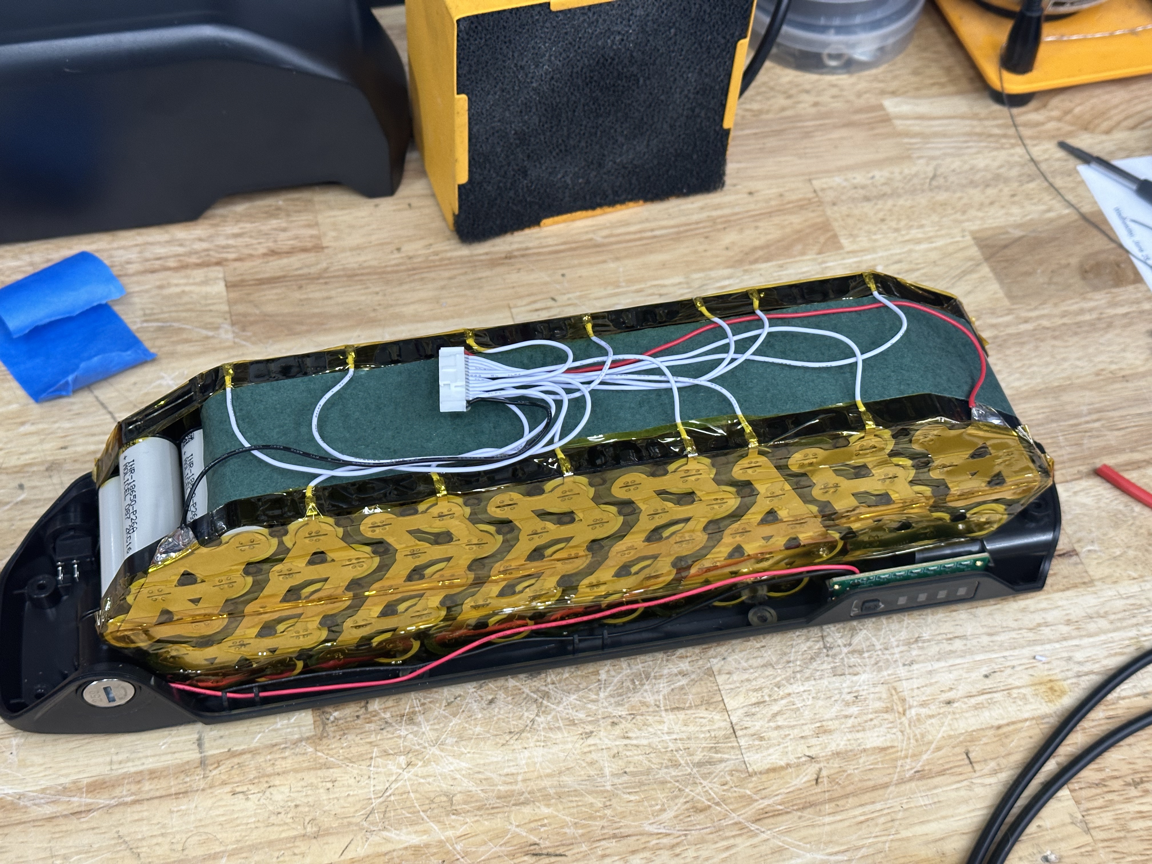
A simple step, but always important. is getting all the balance leads connected to each individual parallel group.
Ok, a lot of work got covered here, such as:
- Connecting the BMS
- Soldering the…
- negative and positive leads of the cell groups to the output pins
- charge port connector to the bms
- bms to the switch
- LED power meter to the neg/pos locations
- Positioning the temp probe in a reasonable location (mid pack as best you can)
All the while being mindful of how wires are crossing and managing to keep it all stuffed into the space the case offers.

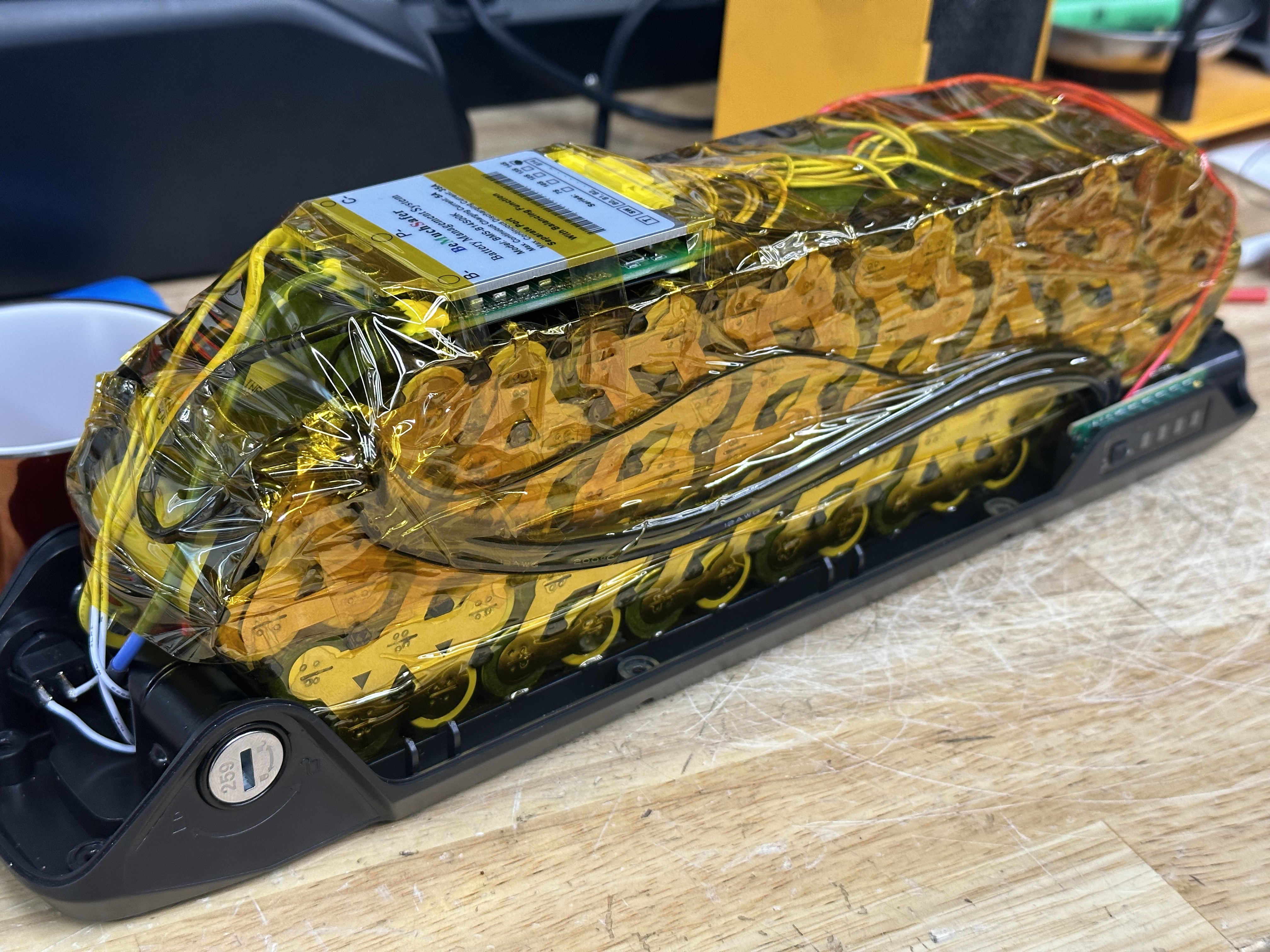
This was a tight fit. I genuinely needed to use some clamps to help me assemble this case – mostly owing to the multiple, large gauge cables used internally. If you’re going to push 100A, you need the copper. Ultimately got it nice and buttoned up, though, so yay.

And, of course, you need to put some kind of notice on the battery about it’s build characteristics. I like to include the layout (serial/parallel), amp hours, watt hours, max amp draw, cells used, and date built. For this build, I also added a little extra cautionary info about the BMS bypass.
More from The Purple Bike:
- Overview (Jun 1, 2023)
- Battery Build, Part 1 (Jun 29, 2023)
- Battery Build, Part 2 (Jun 30, 2023)
- Wiring & Tuning (Jul 1, 2023)